Kia Sportage: Cylinder Block / Cylinder Block Repair procedures
Kia Sportage QL (2015-2025) Service Manual / Engine Mechanical System / Cylinder Block / Cylinder Block Repair procedures
| Disassembly |
In case of removing the high pressure fuel pump, high pressure fuel
pipe, delivery pipe, and injector, there may be injury caused by leakage
of the high pressure fuel. So don’t do any repair work right after engine
stops.
|
|
Mark all wiring and hoses to avoid misconnection
|
| 1. |
Remove the engine assembly from the vehicle.
(Refer to Engine and Transaxle Assembly - “Engine and Transaxle Assembly”)
|
| 2. |
Remove the transaxle assembly from the engine assembly.
(Refer to Automatic Transaxle System - "Automatic Transaxle")
|
| 3. |
Remove the drive plate.
(Refer to Cylinder Block - "Drive Plate")
|
| 4. |
Install the engine to engine stand for disassembly.
|
| 5. |
Remove the intake manifold.
(Refer to Intake and Exhaust System - "Intake Manifold")
|
| 6. |
Remove the exhaust manifold.
(Refer to Intake and Exhaust System - "Exhaust Manifold")
|
| 7. |
Remove the timing chain.
(Refer to Timing System - “Timing Chain”)
|
| 8. |
Remove the cylinder head assembly.
(Refer to Cylinder Head Assembly - "Cylinder Head")
|
| 9. |
Remove the A/C compressor.
(Refer to Heating, Ventilation Air conditioning - "Compressor")
|
| 10. |
Remove the alternator.
(Refer to Engine Electrical System - "Alternator ")
|
| 11. |
Remove the water temperature control assembly.
(Refer to Cooling System - "Water Temperature Control Assembly")
|
| 12. |
Remove the balance shaft & oil pump.
(Refer to Lubrication System - "Balance Shaft & Oil Pump")
|
| 13. |
Remove the ladder frame.
|
| 14. |
Remove the piston & connecting rod assembly.
(Refer to Cylinder Block - "Piston and Connecting Rod")
|
| 15. |
Remove the crankshaft.
(Refer to Cylinder Block - "Crankshaft")
|
| 16. |
Remove the knock sensor.
(Refer to Engine Control/Fuel System - "Knock Sensor")
|
| 17. |
Remove the crankshaft Position Sensor (CKPS).
(Refer to Engine Control/Fuel System - "Crankshaft Position Sensor")
|
| 18. |
Remove the oil pressure sensor.
(Refer to Lubrication System - "Oil Pressure Sensor")
|
| 19. |
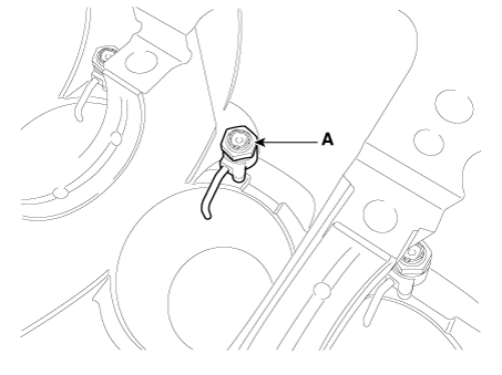
Remove the oil jet (A).
|
| Inspection |
| 1. |
Remove gasket material.
Using a gasket scraper, remove all the gasket material from the top
surface of the cylinder block.
|
| 2. |
Clean cylinder block
Using a soft brush and solvent, thoroughly clean the cylinder block.
|
| 3. |
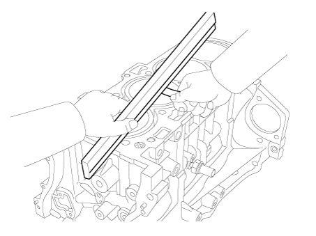
Inspect top surface of cylinder block for flatness.
Using a precision straight edge and feeler gauge, measure the contacting
surface of the cylinder block and the manifolds for warpage.
|
| 4. |
Inspect cylinder bore diameter.
Visually check the cylinder for vertical scratches.
If deep scratches are present, replace the cylinder block.
|
| 5. |
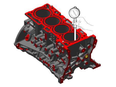
Inspect cylinder bore diameter.
Using a cylinder bore gauge, measure the cylinder bore diameter at position
in the thrust and axial directions.
|
| Reassembly |
| 1. |
Install the oil jet (A).
|
| 2. |
Install the oil pressure switch.
(Refer to Lubrication System - "Oil Pressure Switch")
|
| 3. |
Install the crankshaft position sensor (CKPS).
(Refer to Engine Control/Fuel System - "Crankshaft Position Sensor")
|
| 4. |
Install the knock sensor.
(Refer to Engine Control/Fuel System - "Knock Sensor")
|
| 5. |
Install the crankshaft.
(Refer to Cylinder Block - "Crankshaft")
|
| 6. |
Install the piston & connecting rod assembly.
(Refer to Cylinder Block - "Piston and Connecting Rod")
|
| 7. |
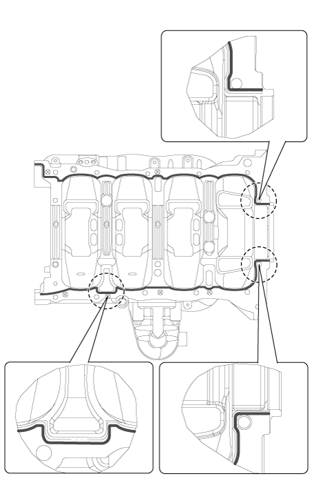
Apply liquid gasket to the mating surface of cylinder block and ladder
frame.
|
| 8. |
Install ladder frame (A) with 10 bolts, in several passes, in sequence
shown.
|
| 9. |
Assemble the other parts in the reverse order of disassembly.
|
 Crankshaft Repair procedures
Disassembly
In case of removing the high pressure fuel pump, high pressure fuel
pipe, delivery pipe, and in ...
Other information:
Kia Sportage QL (2015-2025) Service Manual: Underdrive Brake Control Solenoid Valve (UD/B_VFS) Description and operation
Description • Underdrive brake control solenoid valve is a Variable Force Solenoid (VFS) type. • When TCM supplies variable current to solenoid valve, hydraulic pressure of underdrive brake is controlled by solenoid valve. ...
Kia Sportage QL (2015-2025) Owners Manual: Air bag collision sensors
(1) SRS control module/ Rollover sensor (2) Front impact sensor (3) Side impact sensor (Front Door) (4) Side impact sensor (C-pillar) (5) Side impact sensor (B-pillar) WARNING - Air bag sensors Do not hit or allow any objects to impact the locations where air bags or sensors are instal ...
Copyright © www.ksportagegl.com 2015-2025


