Kia Sportage: Smart Key System / Smart Key Unit Repair procedures
Kia Sportage QL (2015-2025) Service Manual / Body Electrical System / Smart Key System / Smart Key Unit Repair procedures
| Removal |
Smart Key Unit
Take care not to scratch the crash pad and related parts.
|
| [LHD] |
| 1. |
Disconnect the negative (-) battery terminal.
|
| 2. |
Remove the crash pad lower panel.
(Refer to Body - "Crash Pad Lower Panel")
|
| 3. |
Remove the driver's side shower duct (A) after loosening the mounting
screw.
|
| 4. |
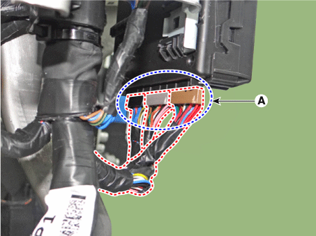
Disconnect the smart key unit connectors (A).
|
| 5. |
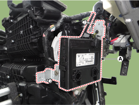
Remove the smart key unit (A) after loosening the mounting bolt and
screw.
|
| [RHD] |
| 1. |
Disconnect the negative (-) battery terminal.
|
| 2. |
Remove the smart junction block (SJB).
(Refer to Fuses And Relays - "Relay Box (Passenger Compartment)")
|
| 3. |
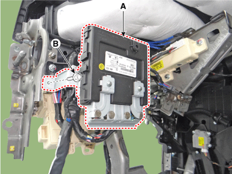
Loosen the smart key unit mounting bolt (A).
|
| 4. |
Remove the smart key unit (A) after loosening the mounting bolt (B).
|
| 5. |
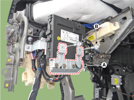
Remove the immobilizer bracket (A) after loosening the mounting bolts
(B).
|
| 6. |
Disconnect the smart key unit connectors (A).
|
Interior 1 Antenna
Take care not to scratch the crash pad and related parts.
|
| 1. |
Disconnect the negative (-) battery terminal.
|
| 2. |
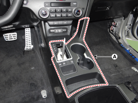
Remove the gear knob & boots (A) pull both of it up.
|
| 3. |
Remove the console upper cover (A) by using a remover.
|
| 4. |
Disconnect the console upper cover connectors (A).
|
| 5. |
Remove the console front tray (A) after loosening the mounting screws.
|
| 6. |
Disconnect the console front tray connectors (A).
|
| 7. |
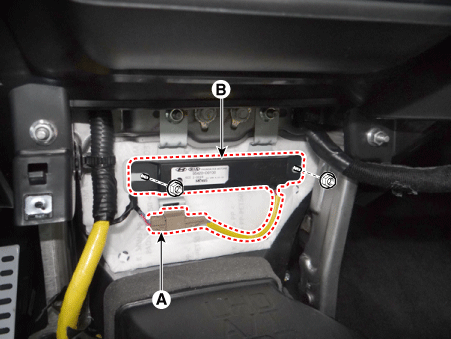
Remove the interior 1 antenna (B) after loosening the mounting nuts
and disconnecting the connector (A).
|
Interior 2 Antenna
| 1. |
Disconnect the negative (-) battery terminal.
|
| 2. |
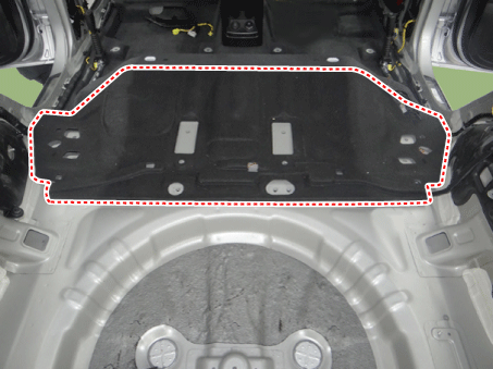
Remove the rear floor carpet.
(Refer to Body - "Floor Carpet")
|
| 3. |
Remove the interior 2 antenna (B) after loosening the mounting nuts
and disconnecting the connector (A).
|
Rear Bumper Antenna
| 1. |
Disconnect the negative (-) battery terminal.
|
| 2. |
Remove the rear bumper cover.
(Refer to Body - "Rear Bumper Cover")
|
| 3. |
Remove the rear bumper antenna (B) after loosening the mounting screws
and disconnecting the connector (A).
|
Buzzer
| 1. |
Disconnect the negative (-) battery terminal.
|
| 2. |
Remove the front left wheel guide.
(Refer to Body - "Front Wheel Guard")
|
| 3. |
Remove the buzzer (A) after disconnecting the connector.
|
Door Outside Handle
| 1. |
Disconnect the negative (-) battery terminal.
|
| 2. |
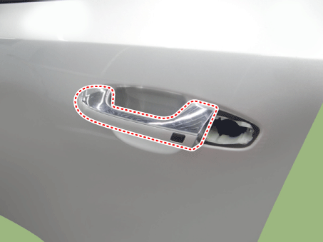
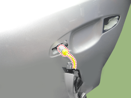
Remove the front door outside handle.
(Refer to Body - "Front Door Outside Handle")
|
Tailgate Open Switch
| 1. |
Disconnect the negative (-) battery terminal.
|
| 2. |
Remove the tailgate trim.
(Refer to Body - "Tailgate Trim")
|
| 3. |
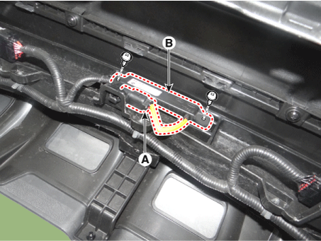
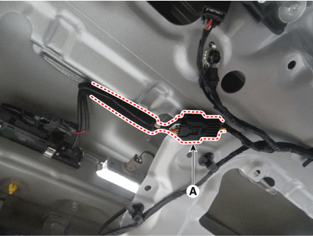
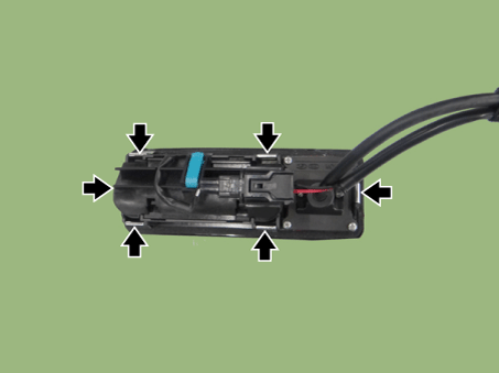
Disconnect the back view camera and tailgate open switch connector (A).
|
| 4. |
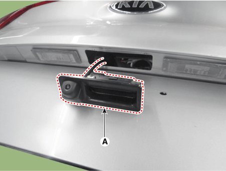
Remove the tailgate open switch assembly (A) after disengaging mounting
clips.
|
| Inspection |
Smart Key Unit
(Refer to Smart Key System - "Smart Key Diagnostic")
Smart Key Switch
(Refer to Smart Key System - "Smart Key Diagnostic")
Antenna
(Refer to Smart Key System - "Smart Key Diagnostic")
Door Outside Handle
| 1. |
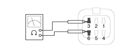
Disconnect the front door outside handle connector (A).
|
| 2. |
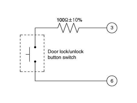
Check for continuity between terminals No 3 and No 6.
|
Tailgate Open Switch
| 1. |
Check for continuity between the tailgate open switch terminals.
|
| 2. |
If continuity is not specified, inspect the switch
|
| Installation |
Smart Key Unit
| [LHD] |
| 1. |
Install the smart key unit.
|
| 2. |
Connect the smart key unit connectors.
|
| 3. |
Install the driver's side shower duct.
|
| 4. |
Install the crash pad lower panel.
|
| 5. |
Install the negative (-) battery terminal and check the smart key system.
|
| [RHD] |
| 1. |
Connect the smart key unit connectors.
|
| 2. |
Install the immobilizer bracket.
|
| 3. |
Install the smart key unit.
|
| 4. |
Install the smart junction block.
|
| 5. |
Install the negative (-) battery terminal and check the smart key system.
|
Interior 1 Antenna
| 1. |
Install the interior 1 antenna.
|
| 2. |
Connect the console front tray connectors.
|
| 3. |
Install the console front tray.
|
| 4. |
Connect the console upper cover connectors.
|
| 5. |
Install the console upper cover.
|
| 6. |
Install the gear knob & boots.
|
| 7. |
Install the negative (-) battery terminal and check the smart key system.
|
Interior 2 Antenna
| 1. |
Install the interior 2 antenna.
|
| 2. |
Install the rear floor carpet.
|
| 3. |
Install the negative (-) battery terminal and check the smart key system.
|
Rear Bumper Antenna
| 1. |
Install the rear bumper antenna.
|
| 2. |
Install the rear bumper cover.
|
| 3. |
Install the negative (-) battery terminal and check the smart key system.
|
Buzzer
| 1. |
Install the buzzer.
|
| 2. |
Install the front left wheel guide.
|
| 3. |
Install the negative (-) battery terminal and check the smart key system.
|
Door Outside Handle
| 1. |
Install the front door outside handle.
|
| 2. |
Install the negative (-) battery terminal and check the smart key system.
|
Tailgate Open Switch
| 1. |
Install the tailgate open switch assembly.
|
| 2. |
Connect the back view camera and tailgate open switch connector.
|
| 3. |
Install the tailgate trim.
|
| 4. |
Install the negative (-) battery terminal and check the smart key system.
|
 Smart Key Unit Schematic diagrams
Circuit Diagram
...
 Smart Key Diagnostic Repair procedures
Inspection
Self Diagnosis With Scan Tool
It will be able to diagnose defects of SMART KEY system with KDS/GDS quickly.
KDS/GDS can operates actuator forcefully, input/output val ...
Other information:
Kia Sportage QL (2015-2025) Service Manual: Fuel pressure test (low pressure system)
Fuel Pressure Test (Low pressure system) 1. Release the residual pressure in fuel line. (Refer to the Fuel Delivery System - Inspection - "Release Residual Pressure in Fuel Line"). ...
Kia Sportage QL (2015-2025) Service Manual: Hood Latch Release Handle Repair procedures
Replacement 1. Using a remover, remove the hood release handle (A). 2. Install in the reverse order of removal. • ...
Copyright © www.ksportagegl.com 2015-2025


